Arduino UNO Learning Shield
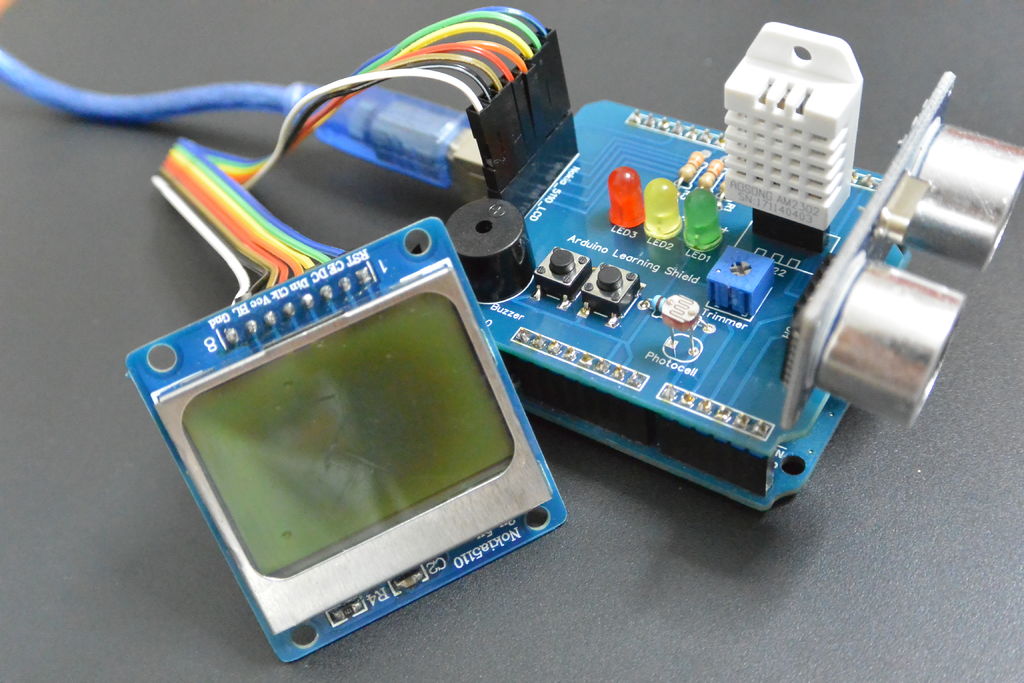
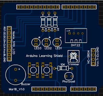
In this guide I will show you how to make your own Arduino learning shield. This learning shield can be useful at schools, universities and to everyone that want to start dealing with the Arduino. With this shield you will learn how to read the temperature and humidity from DHT-22 sensor, read an object distance by using the HC-SR04 ultrasonic sensor, print sensor values to the NOKIA 5110 LCD. On this PCB board you will also find three LEDs, two buttons, buzzer, trimmer and photocell sensor!
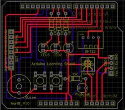
Bellow you will find the PCB layout so you can easily produce it.
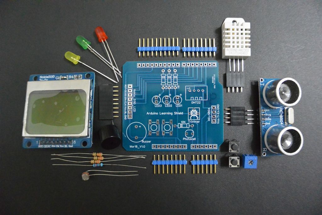
Step 1: What You Will Need – Hardware
Step 2: Connections – Pinout Reference
- Arduino UNO pin 9 –> LED1
- Arduino UNO pin 10 –> LED2
- Arduino UNO pin 11 –> LED3
- Arduino UNO pin 13 –> Buzzer
- Arduino UNO pin 8 –> Push Button1
- Arduino UNO pin 12 –> Push Button2
- Arduino UNO pin 2–> DHT-22 Sensor
- Arduino UNO pin A0 –> Photocell
- Arduino UNO pin A1 –> Trimmer ( Potentiometer )
Ultrasonic Sensor HC-SR04
- Arduino UNO pin A3 –> Triger
- Arduino UNO pin A2 –> Echo
Nokia 5110 LCD (Blue PCB)
- Arduino UNO pin 3 –> CLK
- Arduino UNO pin 4 –> Din
- Arduino UNO pin 5 –> DC
- Arduino UNO pin 6 –> CE
- Arduino UNO pin 7 –> RST
Step 3: How Can I Get This PCB Board
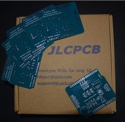
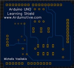
Download the gerber zip file from here and enter here to produce your PCB board.
Use JLCPCB for $2 PCB Fabrication & 2-day Build Time, the quality is really good, check the above photo of our pcb board.
Step 4: Example 1: Temperature, Humidity and Brightness
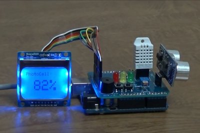
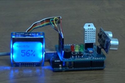
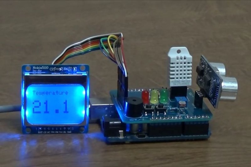
Example 1:
Read and print to the LCD the room temperature, humidity and brightness percentage.
We will use:
Connections – pinout reference
DHT-22 sensor and photocell
- Arduino UNO pin 2–> DHT-22 Sensor
- Arduino UNO pin A0 –> Photocell
Nokia 5110 LCD (Blue PCB)
- Arduino UNO pin 3 –> CLK
- Arduino UNO pin 4 –> Din
- Arduino UNO pin 5 –> DC
- Arduino UNO pin 6 –> CE
- Arduino UNO pin 7 –> RST
The Code
We will use the DHT.temperature and DHT.humidity for reading temperature and humidity from DHT-22 sensor, analogRead for brightness level and display.print to print the values to the display.
Download the code from here and open it with Arduino IDE. Inside you will also find the library files.
Step 5: Example 2: Simulate Park Assist
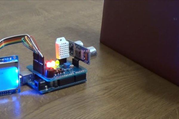
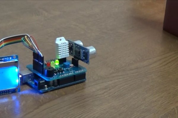
Example 2:
Simulate the car park assist system. Detect an item, blink the LEDs and make a buzzer tone. Use the LCD to print the distance from the incoming object.
http://www.ardumotive.com/ardumotive-learning-shield-en/ardumotive-shield-simulate-park-assist
We will use:
Connections – pinout reference
LEDs and Buzzer
- Arduino UNO pin 9 –> LED1
- Arduino UNO pin 10 –> LED2
- Arduino UNO pin 11 –> LED3
- Arduino UNO pin 13 –> Buzzer
Ultrasonic Sensor HC-SR04
- Arduino UNO pin A3 –> Triger
- Arduino UNO pin A2 –> Echo
Nokia 5110 LCD (Blue PCB)
- Arduino UNO pin 3 –> CLK
- Arduino UNO pin 4 –> Din
- Arduino UNO pin 5 –> DC
- Arduino UNO pin 6 –> CE
- Arduino UNO pin 7 –> RST
The Code
We will use the ultrasonic.Ranging(CM) to read the distance from the HC-SR04 sensor, digitalWrite to turn the LED’s ON and diplay.print to print the distance.
Download the code from here and open it with Arduino IDE. Inside you will also find the library files.
Step 6: Example 3: Blink LEDs
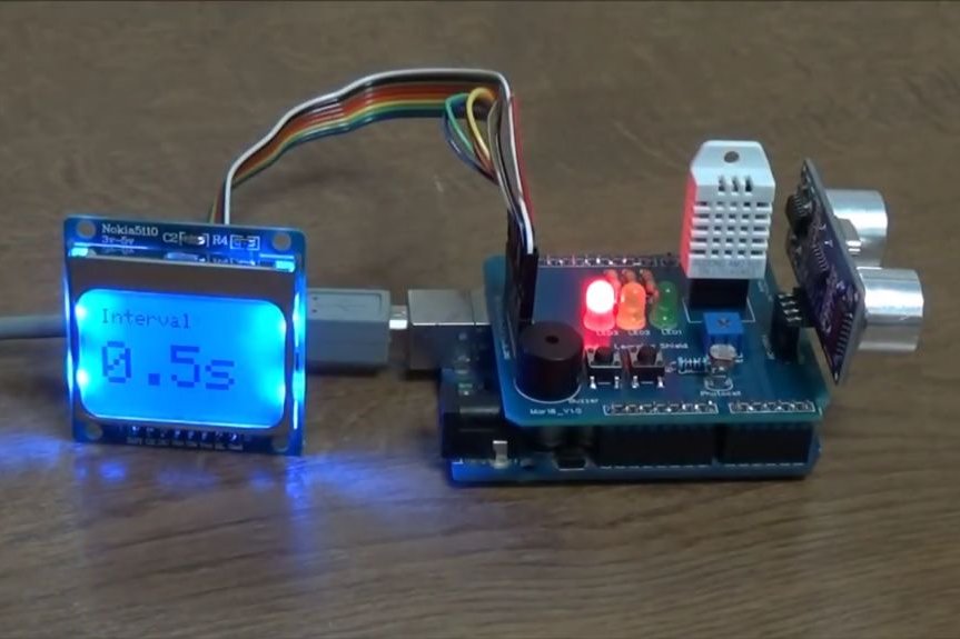
Example 3:
Turn on the LEDs separately and control the changing time with two buttons.Print the interval time to LCD.
http://www.ardumotive.com/ardumotive-learning-shield-en/ardumotive-shield-blink-leds
We will use:
Connections – pinout reference
LEDs and Buttons
- Arduino UNO pin 9 –> LED1
- Arduino UNO pin 10 –> LED2
- Arduino UNO pin 11 –> LED3
- Arduino UNO pin 8 –> Push Button1
- Arduino UNO pin 12 –> Push Button2
Nokia 5110 LCD (Blue PCB)
- Arduino UNO pin 3 –> CLK
- Arduino UNO pin 4 –> Din
- Arduino UNO pin 5 –> DC
- Arduino UNO pin 6 –> CE
- Arduino UNO pin 7 –> RST
The Code
We will use the currentMillis = millis to blink the LED’s without delay function.
Download the code from here and open it with Arduino IDE. Inside you will also find the library files.
Step 7: Example 4: Fade LEDs
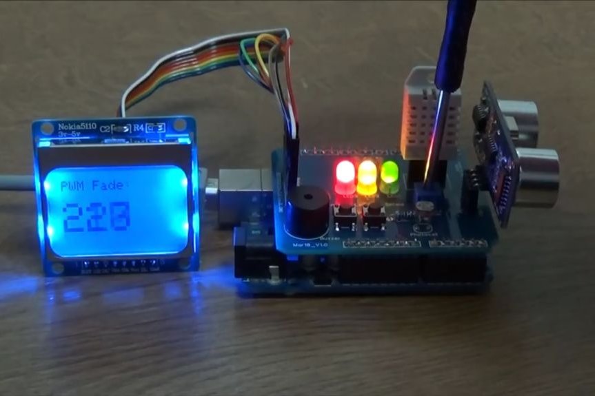
Example 4:
Fade the LEDs with the trimmer. Use the LCD to print the selected PWM value.
http://www.ardumotive.com/ardumotive-learning-shield-en/ardumotive-shield-fade-leds
We will use:
Connections – pinout reference
LEDs and Trimmer
- Arduino UNO pin 9 –> LED1
- Arduino UNO pin 10 –> LED2
- Arduino UNO pin 11 –> LED3
- Arduino UNO pin A1 –> Trimmer ( Potentiometer )
Nokia 5110 LCD (Blue PCB)
- Arduino UNO pin 3 –> CLK
- Arduino UNO pin 4 –> Din
- Arduino UNO pin 5 –> DC
- Arduino UNO pin 6 –> CE
- Arduino UNO pin 7 –> RST
The Code
We will use the analogRead to read the value from Trimmer – potentiometer, map function to re-map analog avalues 0-1023 to PWM values 0-255, analogWrite will send the PWM value to LED’s.
Download the code from here and open it with Arduino IDE. Inside you will also find the library files.
Step 8: That’s It
