DHT11 Temperature and Humidity Sensor Interfacing with Arduino
In this post i will show how to measure temperature and humidity with the help of DHT11 Temperature and Humidity Sensor, in the first part of this post we will use Arduino and its DHT Library to measure the temperature and humidity, and in the next part we will develop our library to sense the temperature and humidity using DH11 sensor.
DH11 sensor is very basic and slow sensor, but are great for hobbyists who want to do some basic data logging. The DHT sensors are made of two parts, a capacitive humidity sensor and a thermistor. There is also a very basic chip inside that does some analog to digital conversion and spits out a digital signal with the temperature and humidity. The digital signal is fairly easy to read using any micro-controller.
DHT11 Features
- Ultra-low cost
- 3 to 5V power and I/O
- 2.5mA max current use during conversion (while requesting data)
- Good for 20-80% humidity readings with 5% accuracy
- Good for 0-50°C temperature readings ±2°C accuracy
- No more than 1 Hz sampling rate (once every second)
- Body size 15.5mm x 12mm x 5.5mm
- 4 pins with 0.1″ spacing
Before proceeding further, I want to ask a question what is Humidity ? Oh you guys don’t know, then read below, even you know, it’s still better to read it.
The DHT11 humidity and temperature sensor measures relative humidity (RH) and temperature. Relative humidity is the ratio of water vapor in air vs. the saturation point of water vapor in air. The saturation point of water vapor in air changes with temperature. Cold air can hold less water vapor before it is saturated, and hot air can hold more water vapor before it is saturated.
The formula for relative humidity is as follows:Relative Humidity = (density of water vapor / density of water vapor at saturation) x 100%
Basically, relative humidity is the amount of water in the air compared to the amount of water that air can hold before condensation occurs. It’s expressed as a percentage. For example, at 100% RH condensation (or rain) occurs, and at 0% RH, the air is completely dry.
Now the next question arises, how the DHT11 Measures Humidity and Temperature?
The DHT11 calculates relative humidity by measuring the electrical resistance between two electrodes. The humidity sensing component of the DHT11 is a moisture holding substrate with the electrodes applied to the surface. When water vapor is absorbed by the substrate, ions are released by the substrate which increases the conductivity between the electrodes. The change in resistance between the two electrodes is proportional to the relative humidity. Higher relative humidity decreases the resistance between the electrodes while lower relative humidity increases the resistance between the electrodes. Inside the DHT11 you can see electrodes applied to a substrate on the front of the chip.
The DHT11 converts the resistance measurement to relative humidity on an IC mounted to the back of the unit and transmits the humidity and temperature readings directly to the Arduino. This IC also stores the calibration coefficients and controls the data signal transmission between the DHT11 and the Arduino or any other micro-controller you use.
The temperature readings from the DHT11 come from a surface mounted NTC temperature sensor (thermistor) built into the unit.
The DHT11 uses one signal wire to transmit sensor readings to the Arduino digitally. The power comes from separate 5V and ground wires. A 5K – 10K Ohm pull-up resistor is connected from the signal line to 5V to make sure the signal level stays high by default.
There are two different variations of the DHT11 sensor you might come across. One type has four pins, and the other type is mounted to a small PCB that has three pins. The PCB mounted version with three pins is nice since it includes a surface mounted 10K Ohm pull up resistor for the signal line, and i am going to use that.
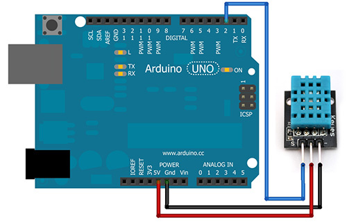
Connection with Arduino
 |
| Connection Diagram |
Communication with the DHT11 Sensor
The interesting thing in this module is the protocol that uses to transfer data. All the sensor readings are sent using a single wire bus which reduces the cost and extends the distance. In order to send data over a bus you have to describe the way the data will be transferred, so that transmitter and receiver can understand what says each other. This is what a protocol does. It describes the way the data are transmitted. On DHT-11 the 1-wire data bus is pulled up with a resistor to VCC. So if nothing is occurred the voltage on the bus is equal to VCC. Communication Format can be separated into three stages.
- Request
- Respond
- Data
Request Stage
To make the DHT-11 to send you the sensor readings you have to send it a request. The request is, to pull down the bus for more than 18ms in order to give DHT time to understand it and then pull it up for 40uS.
Logic Analyzer snaps are attached below.
| 18ms Request |
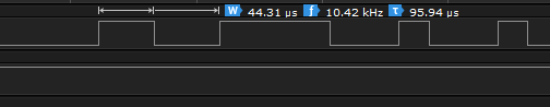 |
| 40usec Response |
Respond Stage
What comes after the request is the DHT-11 response. This is an automatic reply from DHT which indicates that DHT received your request. The response is ~54uS low and 80uS high
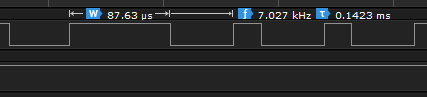 |
| 50usec Low and 80usec High |
Data Stage
What will come after the response is the sensor data. The data will be packed in
a packet of 5 segments of 8-bits each. Totally 5×8 =40bits.
First two segments are Humidity read, integral & decimal. Following two are Temperature read in Celsius, integral & decimal and the last segment is the Check Sum which is the sum of the 4 first segments. If Check Sum’s value isn’t the same as the sum of the first 4 segments that means that data received isn’t correct.
Low Pulse for 54usec and High for 24usec means Bit 0.
Low Pulse for 54usec and High for 70usec means Bit 1.
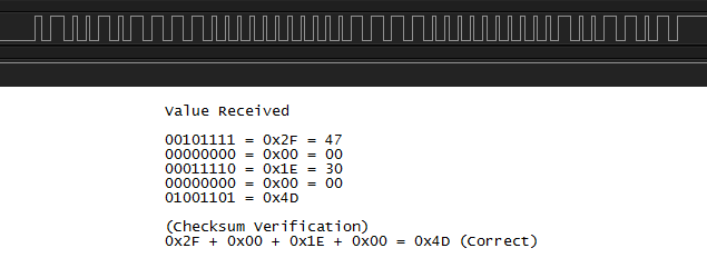 |
| Decoding Data |
You have to install the DHT11 Library, click here to download library.
Arduino Source Code
 #include <dht11.h>
 dht11 DHT11;
 void setup()
 {
  DHT11.attach(5);
  Serial.begin(9600);
  Serial.println("DHT11 TEST PROGRAM ");
  Serial.print("LIBRARY VERSION: ");
  Serial.println(DHT11LIB_VERSION);
 }
 void loop()
 {
  Serial.println("\n");
  int chk = DHT11.read();
  switch (chk)
  {
   case 0:
   Serial.print("Humidity (%): ");
   Serial.println(DHT11.humidity, DEC);
   Serial.print("Temperature (C): ");
   Serial.println(DHT11.temperature, DEC);
   break;
   case -1: Serial.println("Checksum error"); break;
   case -2: Serial.println("Time out error"); break;
   default: Serial.println("Unknown error"); break;
  }
  delay(2000);
 }
 |
| Working Demo |
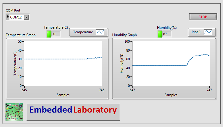 |
| LabVIEW VI |
Following video contains the complete description on how to use DHT11 sensor along with LabVIEW GUI Demo and DHT11 Timings Demonstration using Logic Analyzer.