Turn Any Appliance into a Smart Device with an Arduino Controlled Power Outlet
One of the most useful things you can do with an Arduino is use it to control higher voltage electronic devices. Any device you normally plug into a wall outlet can be activated by a sensor or controlled in other ways with the Arduino. The possibilities are endless considering the variety of sensors and modules available to us today.
In this tutorial, we’ll be using a 5V relay to switch the current to a power outlet on and off. We’ll use the Arduino and a sensor to control when the relay switches. To learn more about the 5V relay and it’s different modes of operation, see our article “How to Set Up a 5V Relay on the Arduino“.
We could always wire the relay directly to the device we want to control, but it’s more practical to go one step closer to the source and switch the power at the outlet. That way you can use it for multiple devices without having to re-wire the relay or cut into the device’s power supply. In this project, we’ll connect a power outlet box to a grounded extension cord and install a 5V relay inside the box so we can control it with the Arduino.
Building the Arduino Controlled Power Outlet
WARNING!! – THIS PROJECT INVOLVES WORKING WITH HIGH VOLTAGES THAT CAN CAUSE SERIOUS INJURY, DEATH, AND/OR SET YOUR HOUSE ON FIRE. PLEASE PROCEED WITH CAUTION, AND ALWAYS MAKE SURE CIRCUITS ARE UN-PLUGGED BEFORE WORKING ON THEM.
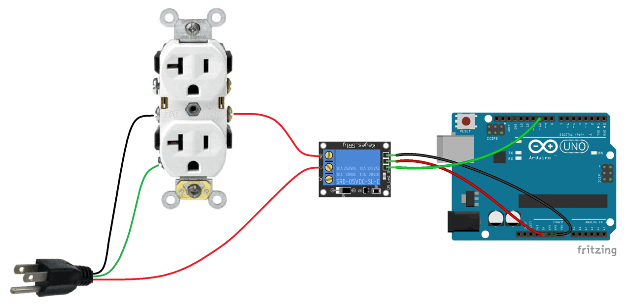
We will install the 5V relay in-line with the positive (hot) wire of the 120-240V power outlet in the normally open configuration. The negative (neutral) wire and the ground wire will be connected directly from the power cord to the outlet. The 5V relay will turn on the current to the outlet whenever it receives a 5V signal from the Arduino.
Here’s a diagram that outlines the connections:
Gather the Parts
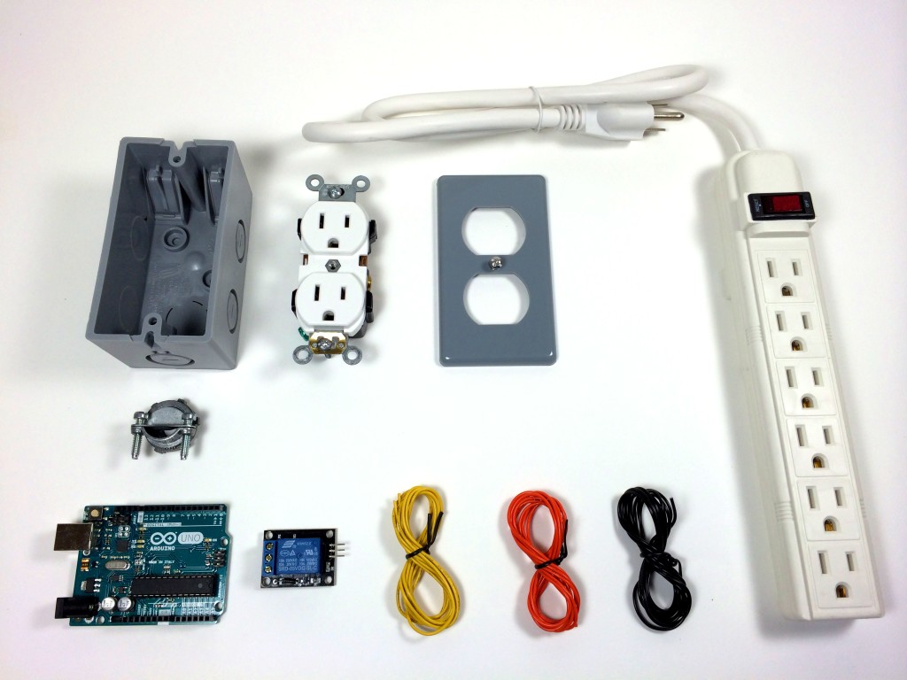
The parts I used are listed below, but you can use other types. This is just what I found at my local Home Depot. I’ve included links to these parts on Amazon so you can get an idea of what they cost, but I got everything (except the Arduino) for under $22.00 USD.
- Electrical Outlet Box (buy it on Amazon | eBay)
- Electrical Outlet (buy it on Amazon | eBay)
- Electrical Outlet Box Cover Plate (buy it on Amazon | eBay)
- 3/8″ NM/SE Connector (buy it on Amazon | eBay)
- Power Strip (buy it on Amazon | eBay)
- SRD-05VDC-SL-C 5V Relay (buy it on Amazon | eBay)
- Signal, Vcc, and Ground Wires (buy it on Amazon | eBay)
- Arduino UNO R3 (buy it on Amazon | eBay)
Constructing the Box
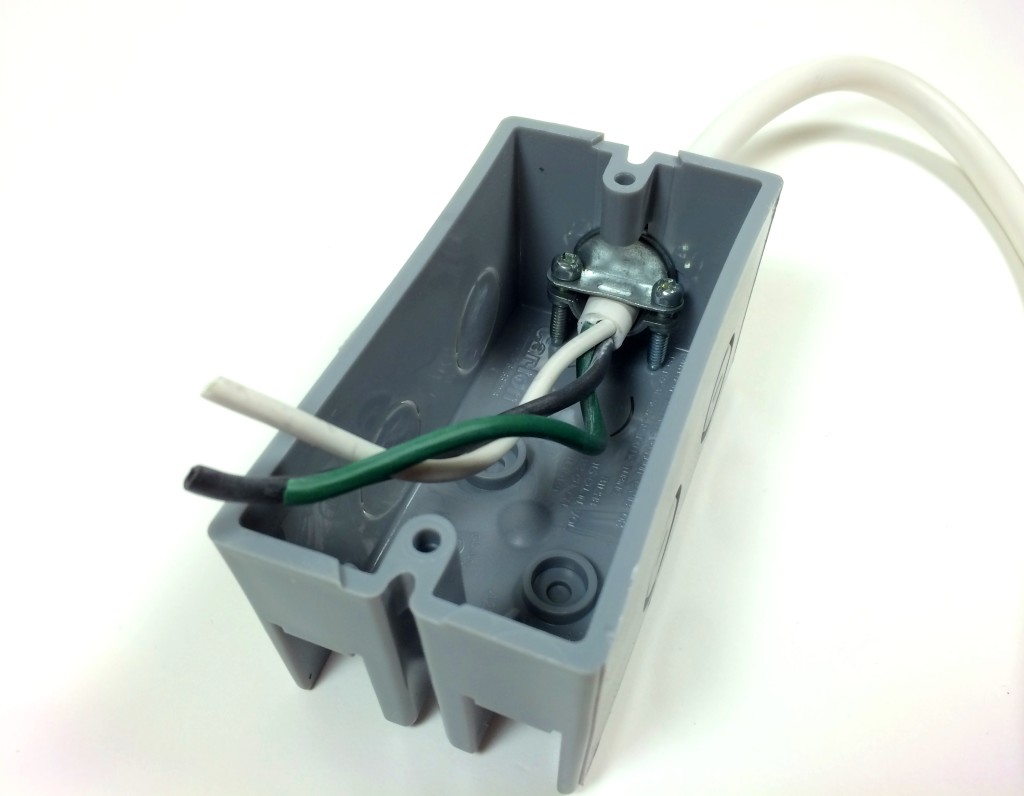
Cut the cord on the power strip and determine which wire connects to each prong on the plug with a homemade continuity tester. My cord has three wires. The neutral (white) wire is connected to the larger prong, the hot (black) wire is connected to the smaller prong, and the ground (green) wire is connected to the round prong:

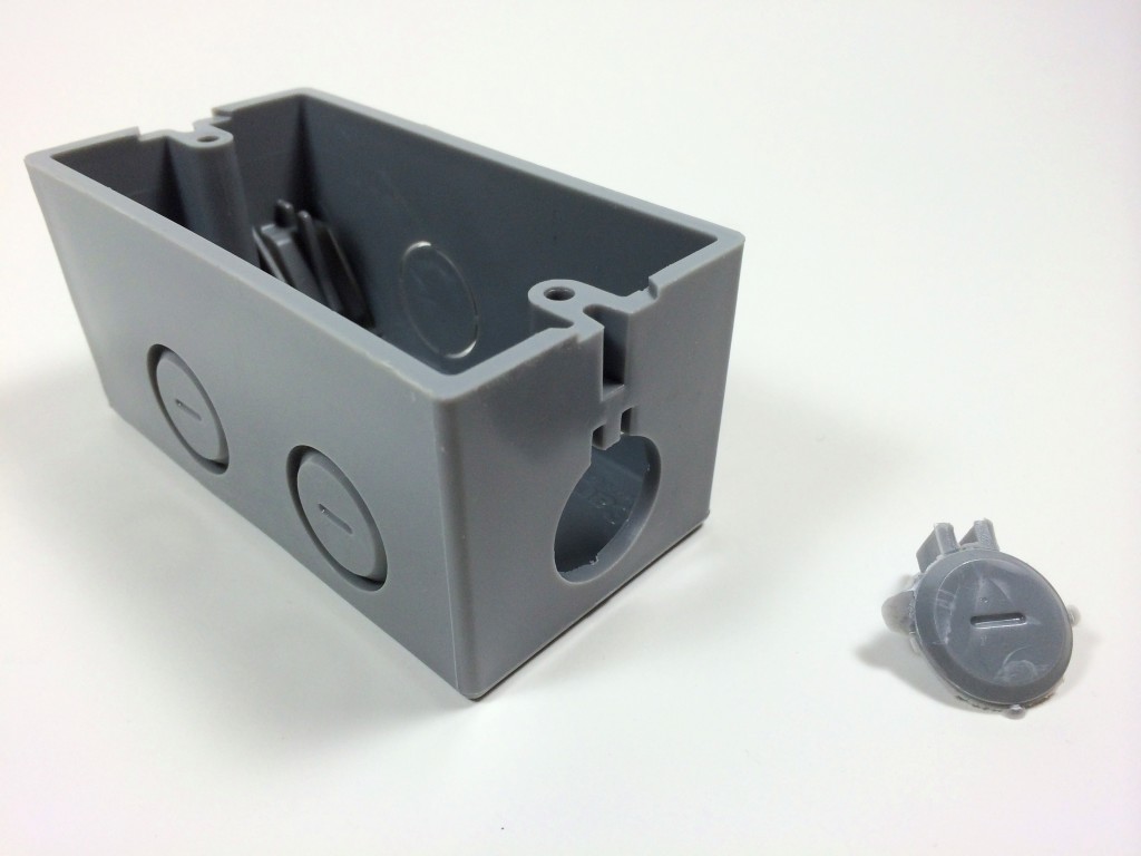
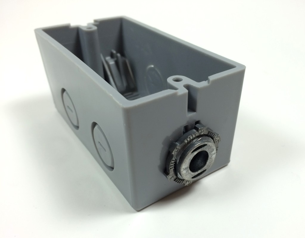
Remove one of the knock out plugs from the electrical outlet box:
Install the NM/SE Connector:
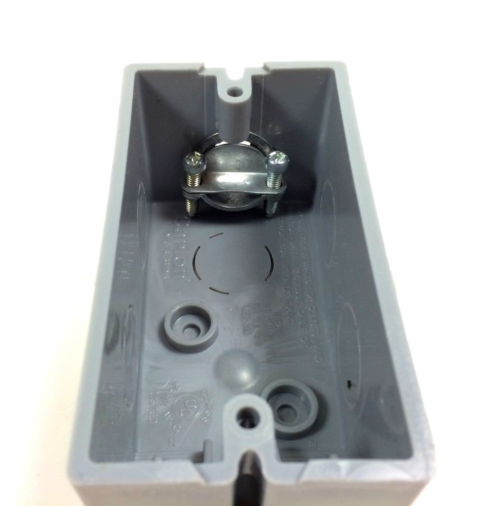
Remove about 3 to 4 inches of the outer plastic sheathing from the electrical cord, then feed it into the box through the NM/SE connector:
Wiring the Relay
Cut a 4 inch piece of the hot wire and strip off about 1/4 inch of the insulation. Insert it into the NO terminal of the relay and tighten the screw on the relay terminal to make a secure connection. Now is a good time to strip the other end of this wire so we can connect it to the electrical outlet later:
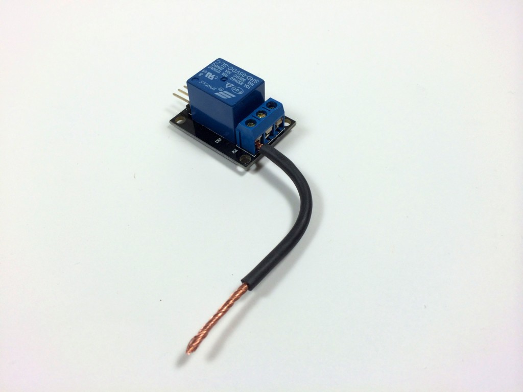
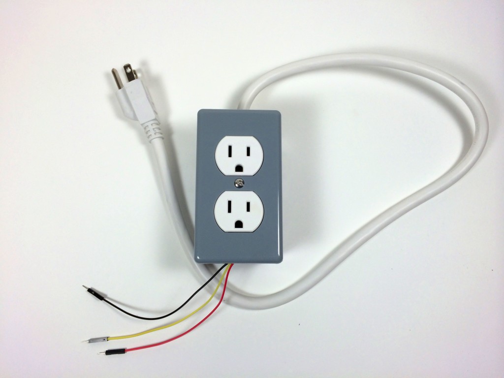
Connect the signal, Vcc, and ground wires to the relay:
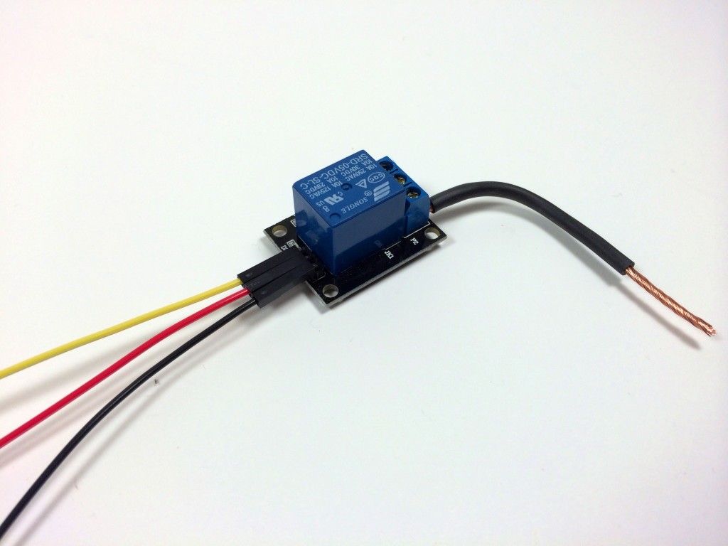
Strip the neutral and ground wires on the electrical cord so they have about 3/4 inch of exposed copper. We’ll connect these to the power outlet later. The hot wire only needs about 1/4 inch since it will be inserted into the C terminal of the relay:
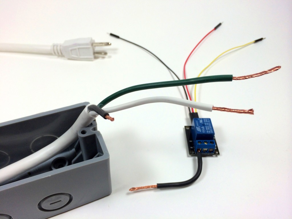
Insert the hot wire from the electrical cord into the common (C) terminal of the relay. Double check that both terminals of the relay are securely screwed down:
Connecting the Hot, Neutral, and Ground Wires to the Electrical Outlet
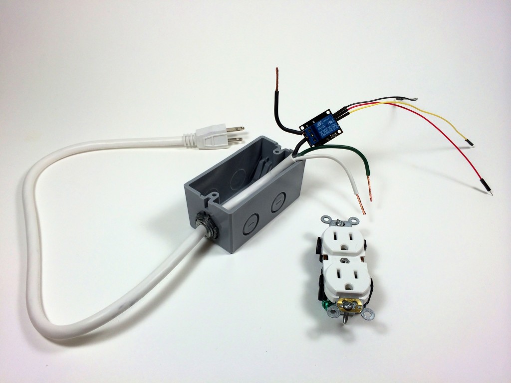
The right side of the power outlet with the smaller slot is the hot side of the outlet. The hot (black) wire from the NO terminal of the relay will be screwed to the hot terminal with one of the gold colored screws:
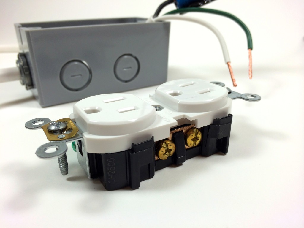
The left side of the outlet with the larger slot is the neutral side. The neutral (white) wire from the power cord will be screwed to the neutral terminal with one of the silver colored screws:
The D shaped slots are for the ground prong. The ground (green) wire from the power cord will be screwed to the ground terminal with the green screw:
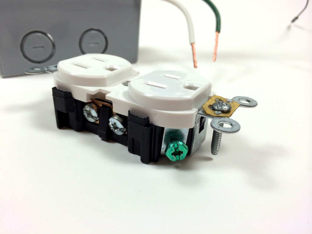
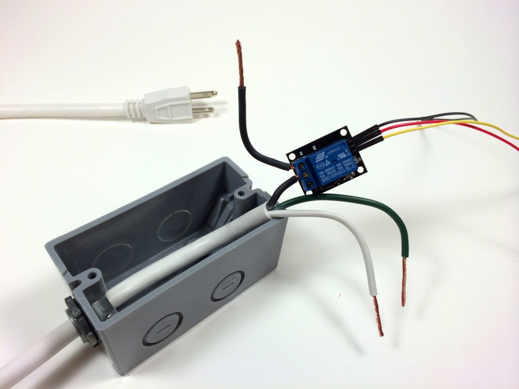
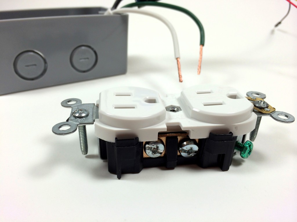
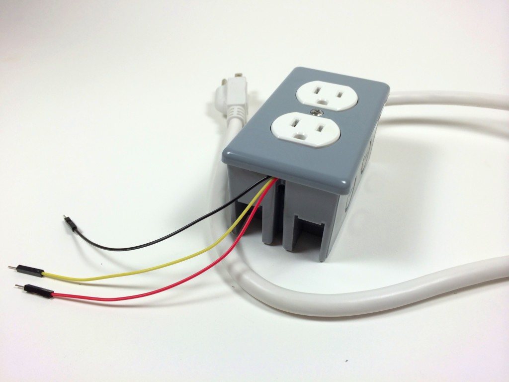
Before connecting the wires to the outlet, position the relay and all of the wires inside the box to make sure it fits well. Now is a good time to trim the wires and tighten the screws on the NM/SE connector:
Now connect the ground wire to the ground terminal of the outlet:
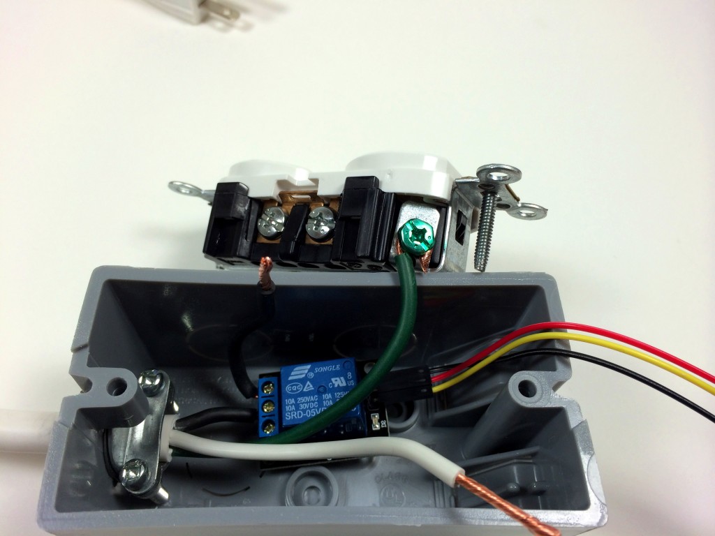
Connect the neutral wire to the neutral terminal of the outlet:
Connect the hot wire from the relay to the hot terminal of the outlet:
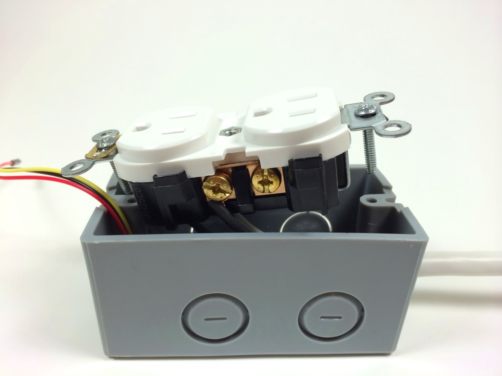
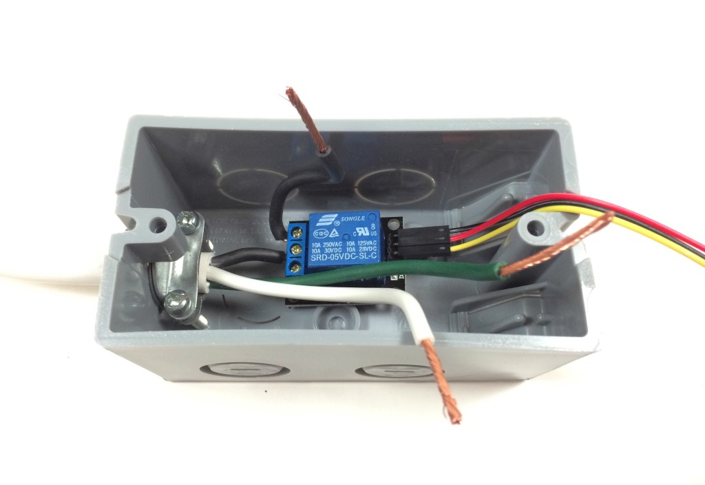
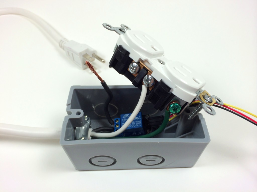
Now that all of the electrical connections have been made we can screw the outlet into place in the electrical outlet box:
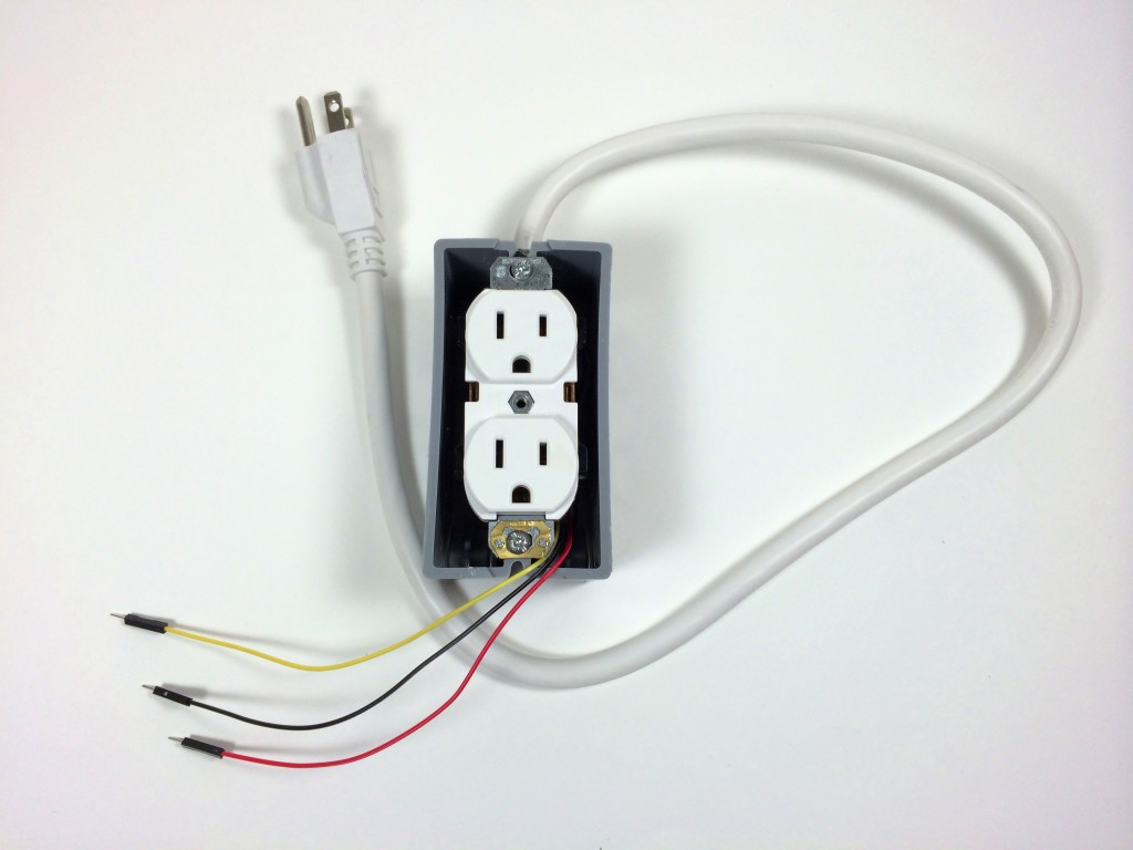
Attach the electrical box cover plate:
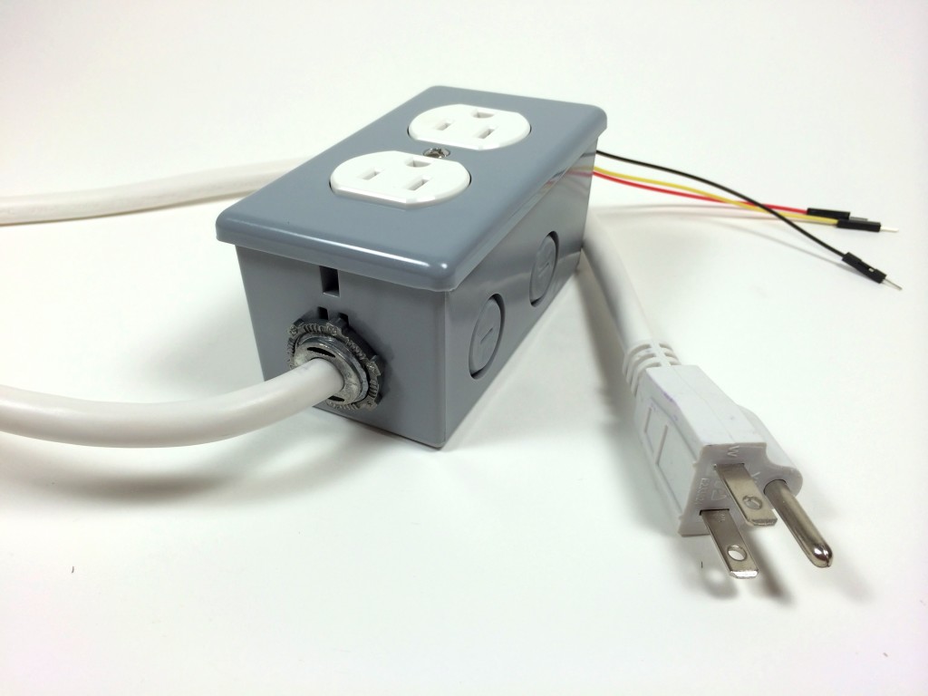
And we’re done. Now we have a 120V electrical outlet that can be controlled by an Arduino. Everything looks clean, and the relay control wires are ready for a breadboard:
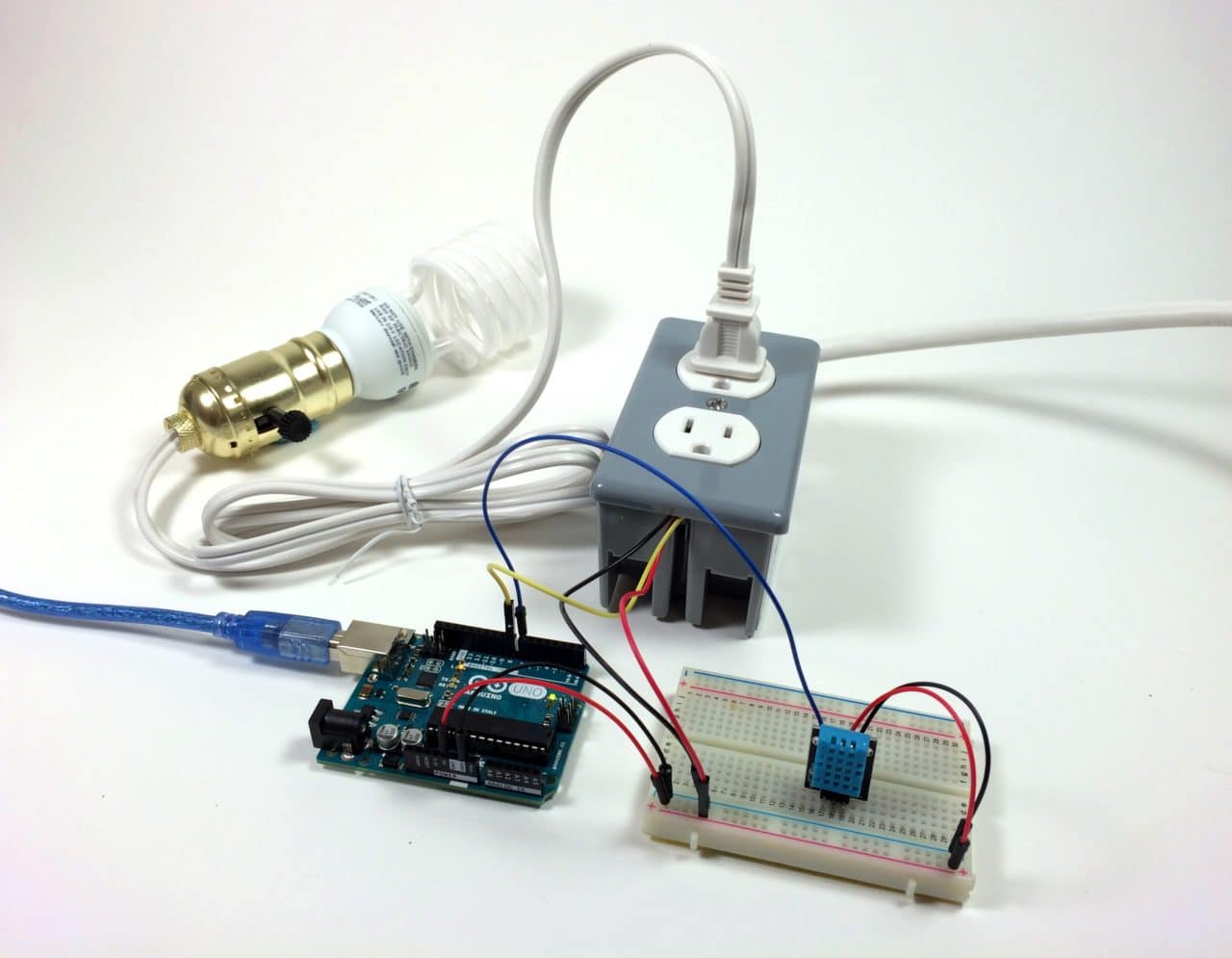
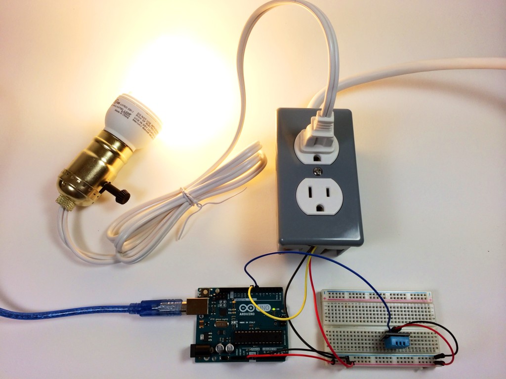
Testing it Out
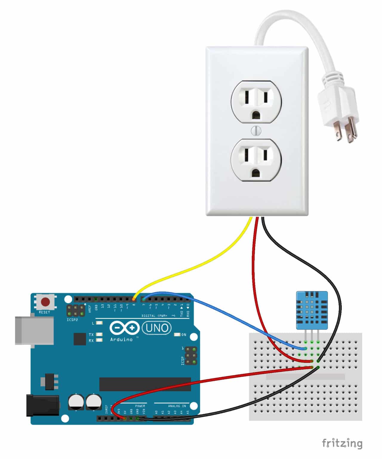
Let’s test out the Arduino controlled power outlet by programming a light fixture to turn off when the humidity gets above a certain point. To make this circuit you’ll need a DHT11 humidity and temperature sensor.
Connecting the Arduino
Follow this diagram to make the connections:

Programming the Arduino
After making all of the connections, we’re ready to program the Arduino. Upload this program to the board to control the outlet with the DHT11:
#include <dht.h>
dht DHT;
#define DHT11_PIN 7
int pinOut = 8;
void setup(){
Serial.begin(9600);
pinMode(8, OUTPUT);
}
void loop()
{
int chk = DHT.read11(DHT11_PIN);
Serial.print(« Temperature = « );
Serial.println(DHT.temperature);
Serial.print(« Humidity = « );
Serial.println(DHT.humidity);
if (DHT.humidity <= 40){
digitalWrite(pinOut, HIGH);
}
else {
digitalWrite(pinOut, LOW);
}
delay(500);
}
This program takes the humidity data output by the DHT11 and tells the Arduino to output a HIGH signal at pin 8 until the humidity reaches 40% or greater. Therefore, the light bulb will be on below 40% relative humidity. If the humidity goes above 40%, the program tells the Arduino to output a LOW signal at pin 8, and the light bulb will be switched off.
You can change the humidity at which the relay turns on/off in line 20 (if (DHT.humidity <= 40){). You can also use the temperature data instead of the humidity (or use both) by changing DHT.humidity to DHT.temperature.
Thanks for reading! This has probably been one of the most useful things I’ve built so far. You should definitely build one for yourself, especially if you’re interested in controlling devices around your home. Let me know in the comments if you have any questions about this project, and be sure to share it if you know someone else that might enjoy it too!