Raspberry Pi DS18B20 Temperature Sensor Tutorial
The DS18B20 temperature sensor is perfect for projects like weather stations and home automation systems. Few sensors are this easy to set up on the Raspberry Pi. They’re the same size as a transistor and use only one wire for the data signal. They’re also extremely accurate and take measurements quickly. The only other component you need is a 4.7K Ohm or 10K Ohm resistor.
In this tutorial, I’ll show you how to connect the DS18B20 to your Raspberry Pi and display the temperature readings on the SSH terminal or an LCD display.
Parts used in this tutorial:
- DS18B20 Digital Temperature Sensor (buy it on Amazon | eBay)
- Raspberry Pi 3 B+ (buy it on Amazon | eBay)
- 16X2 LCD Display (buy it on Amazon | eBay)
Digital Temperature Sensors vs. Analog Temperature Sensors
Digital temperature sensors like the DS18B20 differ from analog thermistors in several important ways. In thermistors, changes in temperature cause changes in the resistance of a ceramic or polymer semiconducting material. Usually, the thermistor is set up in a voltage divider, and the voltage is measured between the thermistor and a known resistor. The voltage measurement is converted to resistance and then converted to a temperature value by the microcontroller.
Digital temperature sensors are typically silicon based integrated circuits. Most contain the temperature sensor, an analog to digital converter (ADC), memory to temporarily store the temperature readings, and an interface that allows communication between the sensor and a microcontroller. Unlike analog temperature sensors, calculations are performed by the sensor, and the output is an actual temperature value.
About the DS18B20
The DS18B20 communicates with the “One-Wire” communication protocol, a proprietary serial communication protocol that uses only one wire to transmit the temperature readings to the microcontroller.
The DS18B20 can be operated in what is known as parasite power mode. Normally the DS18B20 needs three wires for operation: the Vcc, ground, and data wires. In parasite mode, only the ground and data lines are used, and power is supplied through the data line.
The DS18B20 also has an alarm function that can be configured to output a signal when the temperature crosses a high or low threshold that’s set by the user.
A 64 bit ROM stores the device’s unique serial code. This 64 bit address allows a microcontroller to receive temperature data from a virtually unlimited number of sensors at the same pin. The address tells the microcontroller which sensor a particular temperature value is coming from.
Technical Specifications
- -55°C to 125°C range
- 3.0V to 5.0V operating voltage
- 750 ms sampling
- 0.5°C (9 bit); 0.25°C (10 bit); 0.125°C (11 bit); 0.0625°C (12 bit) resolution
- 64 bit unique address
- One-Wire communication protocol
For more details on timing, configuring parasite power, and setting the alarm, see the datasheet:
You can also watch the video version of this tutorial here:
Connect the DS18B20 to the Raspberry Pi
The DS18B20 has three separate pins for ground, data, and Vcc:

Wiring for SSH Terminal Output
Follow this wiring diagram to output the temperature to an SSH terminal:
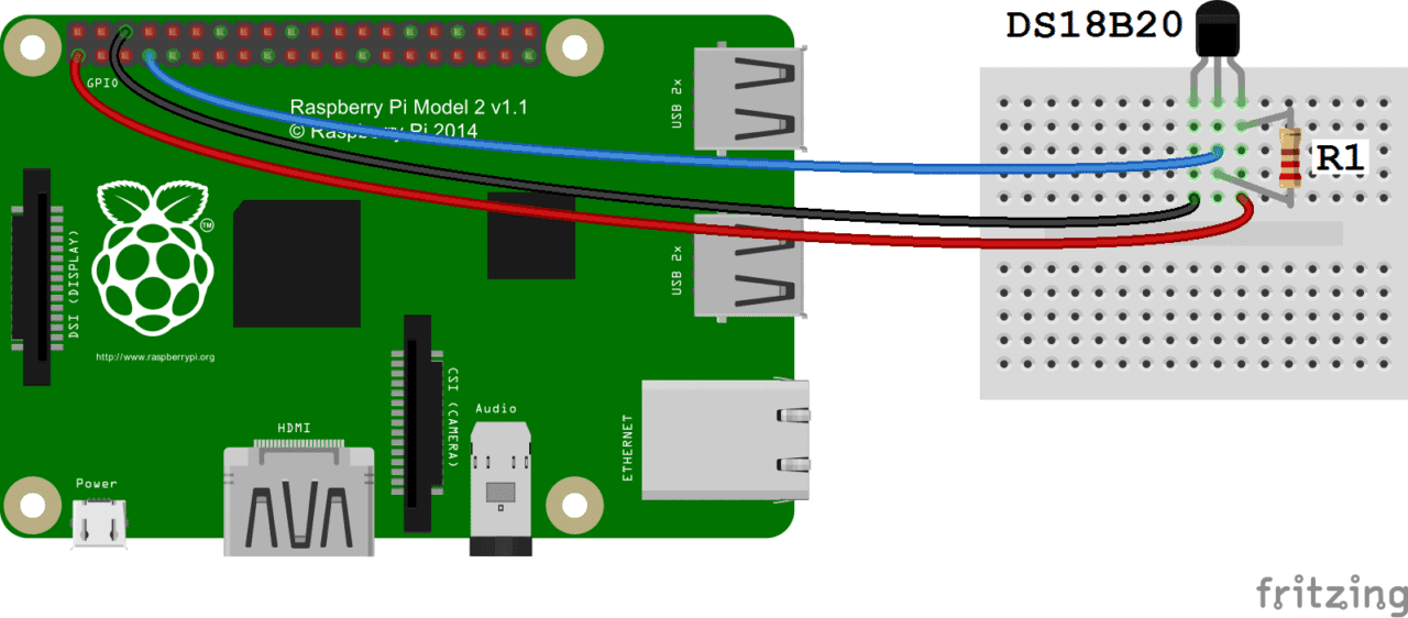
R1: 4.7K Ohm or 10K Ohm resistor
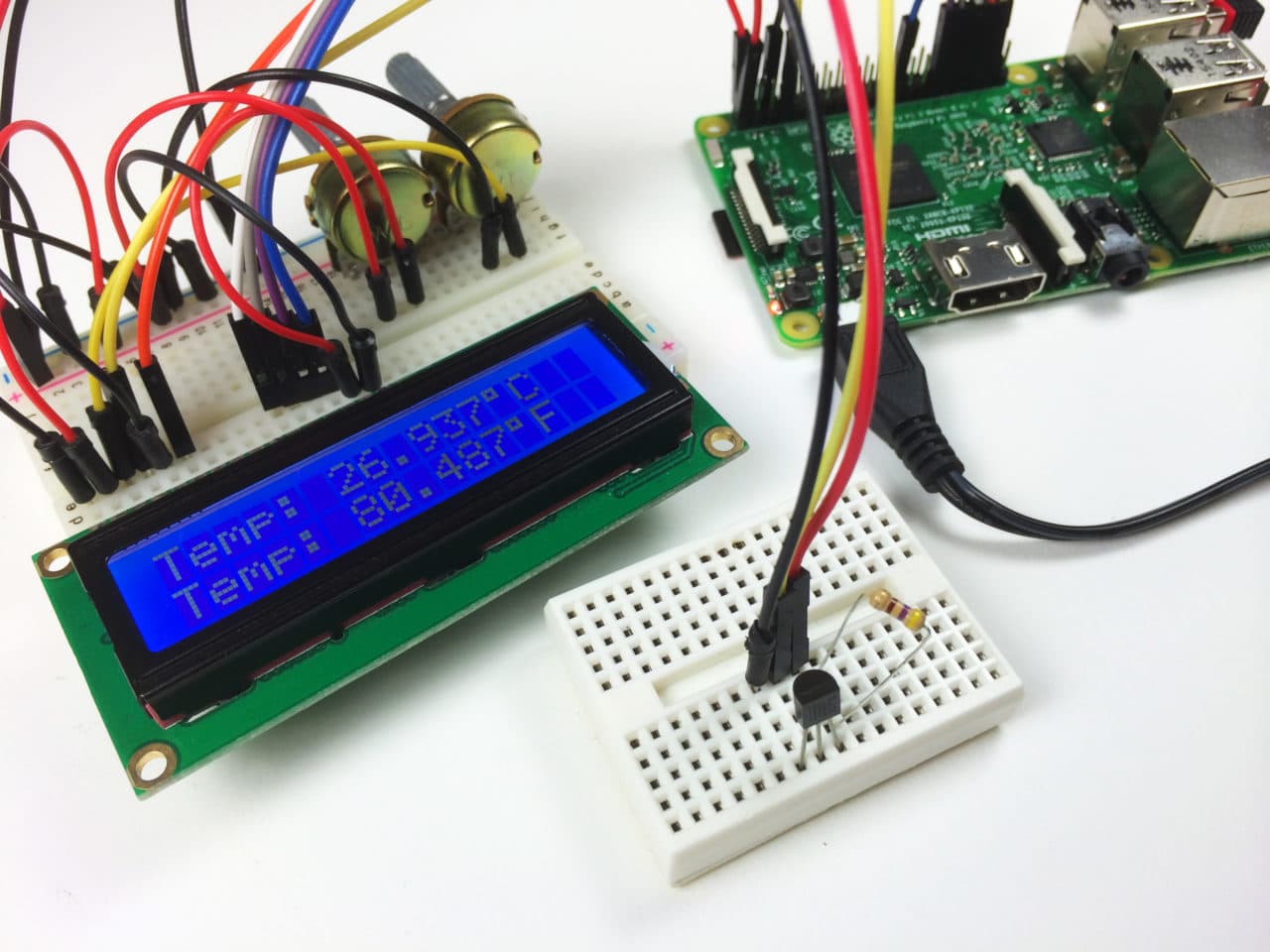
Wiring for LCD Output
Follow this diagram to output the temperature readings to an LCD:

R1: 4.7K Ohm or 10K Ohm resistor
For more information about using an LCD on the Raspberry Pi, check out our tutorial Raspberry Pi LCD Set Up and Programming in Python.
Enable the One-Wire Interface
We’ll need to enable the One-Wire interface before the Pi can receive data from the sensor. Once you’ve connected the DS18B20, power up your Pi and log in, then follow these steps to enable the One-Wire interface:
1. At the command prompt, enter: sudo nano /boot/config.txt, then add this to the bottom of the file:
dtoverlay=w1–gpio
2. Exit Nano, and reboot the Pi (sudo reboot)
3. Log in to the Pi again, and at the command prompt enter sudo modprobe w1–gpio
4. Then enter sudo modprobe w1-therm
5. Change directories to the /sys/bus/w1/devices directory by entering: cd /sys/bus/w1/devices
6. Now enter ls to list the devices:

28-000006637696 w1_bus_master1 is displayed in my case.
7. Now enter cd 28-XXXXXXXXXXXX (change the X’s to your own address)
For example, in my case I would enter: cd 28-000006637696
8. Enter cat w1_slave which will show the raw temperature reading output by the sensor:
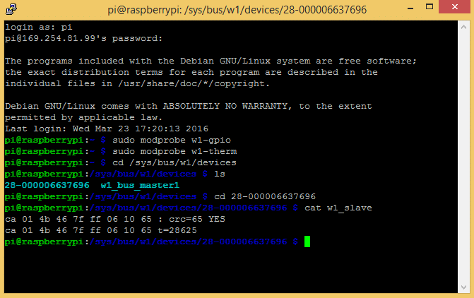
Here the temperature reading is t=28625, which means a temperature of 28.625 degrees Celsius.
9. Enter cd to return to the root directory
That’s all that’s required to set up the one wire interface. Now you can run one of the programs below to output the temperature to an SSH terminal or to an LCD…
Programming the Temperature Sensor
The examples below are written in Python. If this is your first time running a Python program, check out our tutorial How to Write and Run a Python Program on the Raspberry Pi to see how to save and run Python files.
Temperature Output to SSH Terminal
This is a basic Python program that will output the temperature readings in Fahrenheit and Celsius to your SSH terminal:
import os
import glob
import time

os.system('modprobe w1-gpio')
os.system('modprobe w1-therm')

base_dir = '/sys/bus/w1/devices/'
device_folder = glob.glob(base_dir + '28*')[0]
device_file = device_folder + '/w1_slave'

def read_temp_raw():
    f = open(device_file, 'r')
    lines = f.readlines()
    f.close()
    return lines

def read_temp():
    lines = read_temp_raw()
    while lines[0].strip()[-3:] != 'YES':
        time.sleep(0.2)
        lines = read_temp_raw()
    equals_pos = lines[1].find('t=')
    if equals_pos != -1:
        temp_string = lines[1][equals_pos+2:]
        temp_c = float(temp_string) / 1000.0
        temp_f = temp_c * 9.0 / 5.0 + 32.0
        return temp_c, temp_f

while True:
	print(read_temp())
	time.sleep(1)

Temperature Output to an LCD
We’ll be using a Python library called RPLCD to drive the LCD. The RPLCD library can be installed from the Python Package Index, or PIP. PIP might already be installed on your Pi, but if not, enter this at the command prompt to install it:
sudo apt-get install python-pip
After you get PIP installed, install the RPLCD library by entering:
sudo pip install RPLCD
Once you have the library installed, you can run this program to output the temperature to an LCD display:
import os
import glob
import time
from RPLCD import CharLCD
lcd = CharLCD(cols=16, rows=2, pin_rs=37, pin_e=35, pins_data=[33, 31, 29, 23])
os.system(‘modprobe w1-gpio’)
os.system(‘modprobe w1-therm’)
base_dir = ‘/sys/bus/w1/devices/’
device_folder = glob.glob(base_dir + ’28*’)[0]
device_file = device_folder + ‘/w1_slave’
def read_temp_raw():
f = open(device_file, ‘r’)
lines = f.readlines()
f.close()
return lines
#CELSIUS CALCULATION
def read_temp_c():
lines = read_temp_raw()
while lines[0].strip()[-3:] != ‘YES’:
time.sleep(0.2)
lines = read_temp_raw()
equals_pos = lines[1].find(‘t=’)
if equals_pos != -1:
temp_string = lines[1][equals_pos+2:]
temp_c = int(temp_string) / 1000.0 # TEMP_STRING IS THE SENSOR OUTPUT, MAKE SURE IT’S AN INTEGER TO DO THE MATH
temp_c = str(round(temp_c, 1)) # ROUND THE RESULT TO 1 PLACE AFTER THE DECIMAL, THEN CONVERT IT TO A STRING
return temp_c
#FAHRENHEIT CALCULATION
def read_temp_f():
lines = read_temp_raw()
while lines[0].strip()[-3:] != ‘YES’:
time.sleep(0.2)
lines = read_temp_raw()
equals_pos = lines[1].find(‘t=’)
if equals_pos != -1:
temp_string = lines[1][equals_pos+2:]
temp_f = (int(temp_string) / 1000.0) * 9.0 / 5.0 + 32.0 # TEMP_STRING IS THE SENSOR OUTPUT, MAKE SURE IT’S AN INTEGER TO DO THE MATH
temp_f = str(round(temp_f, 1)) # ROUND THE RESULT TO 1 PLACE AFTER THE DECIMAL, THEN CONVERT IT TO A STRING
return temp_f
while True:
lcd.cursor_pos = (0, 0)
lcd.write_string(« Temp: » + read_temp_c() + unichr(223) + « C »)
lcd.cursor_pos = (1, 0)
lcd.write_string(« Temp: » + read_temp_f() + unichr(223) + « F »)

That should just about wrap it up! Hope you found it useful. Be sure to subscribe if you’d like to get an email each time we publish a new tutorial. Feel free to share it if you know someone else that would like it… And as always, let us know in the comments if you have any problems setting it up!